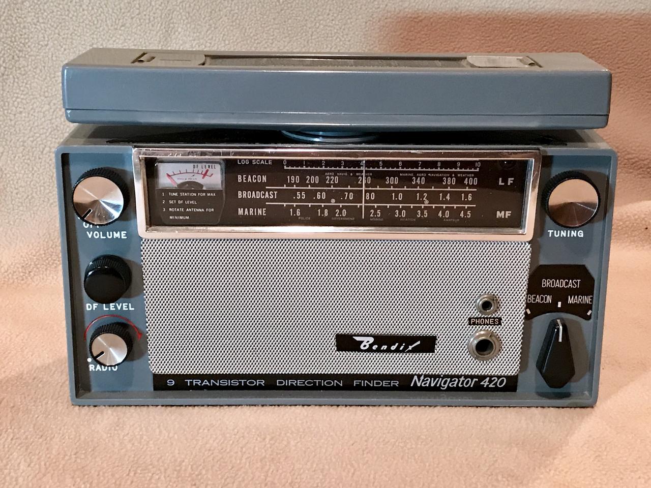
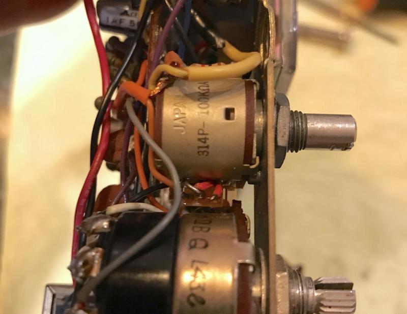
BFO Added
Date: 01/30/18
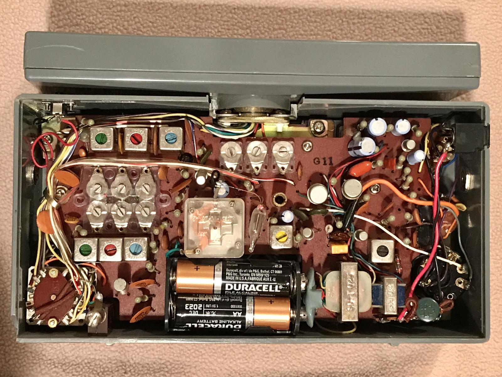
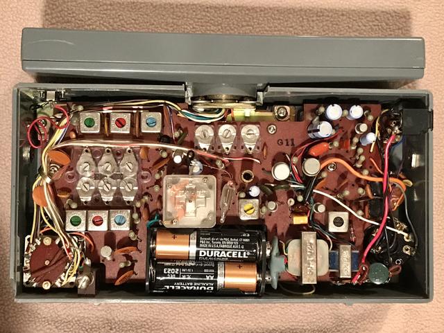
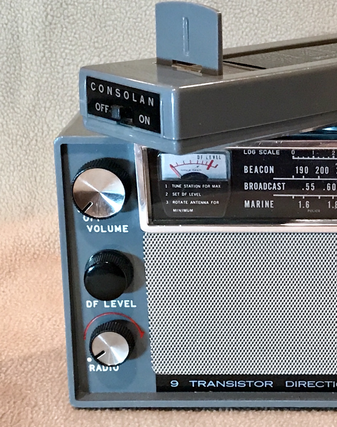
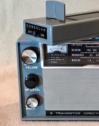
That middle pot wasn't part of the radio originally. It controls the BFO injection level.
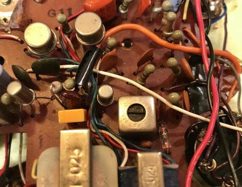
BFO Circuitry
Date: 01/30/18
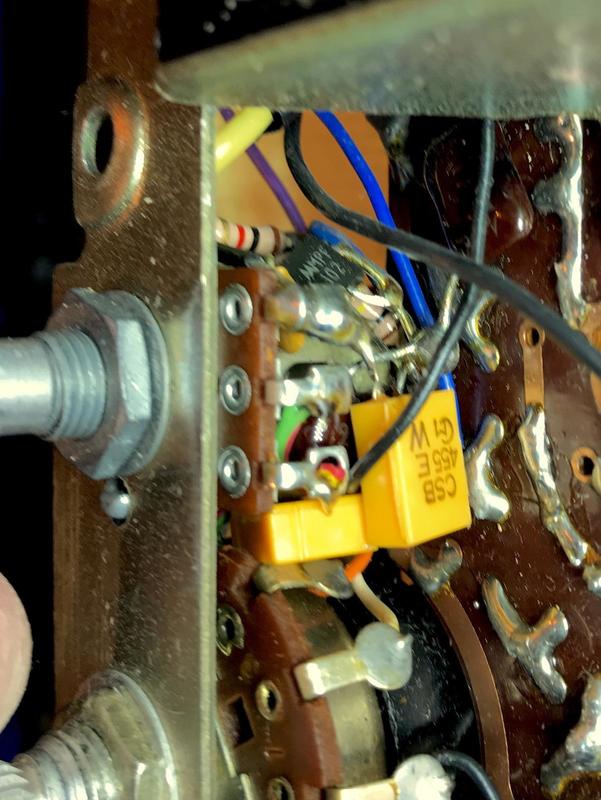
BFO built completely on injection level pot. Main components consist of MPF102 FET, 455 KHz ceramic resonator and 455 KHz ceramic filter.
This BFO is EXTREMELY stable!
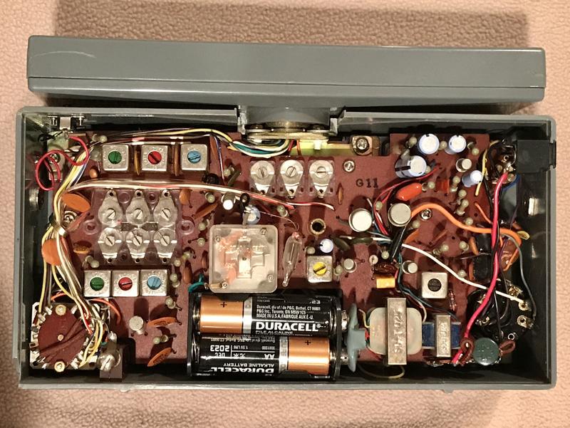
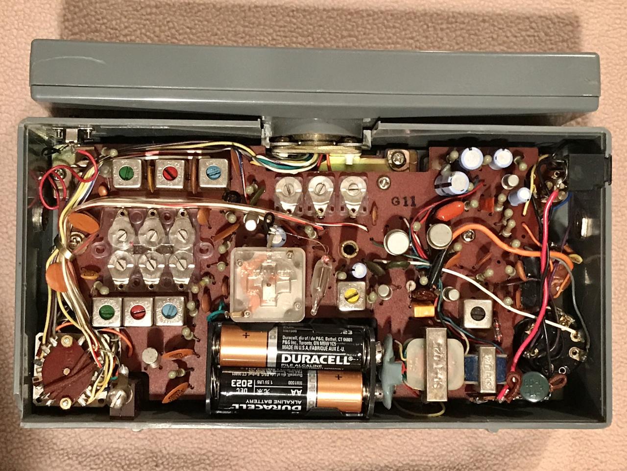
BFO Circuitry View 2
Date: 01/30/18
Another view of BFO with bottom of ceramic filter visible.
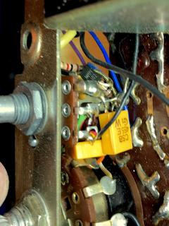
BFO injection and added 455 KHz ceramic fillter
Date: 01/30/18
Orange wire is the output from the BFO injection level pot, connected to IF through silver mica cap. The orange device is a 455 KHz ceramic filter added to the radio's IF chain for better selectivity.
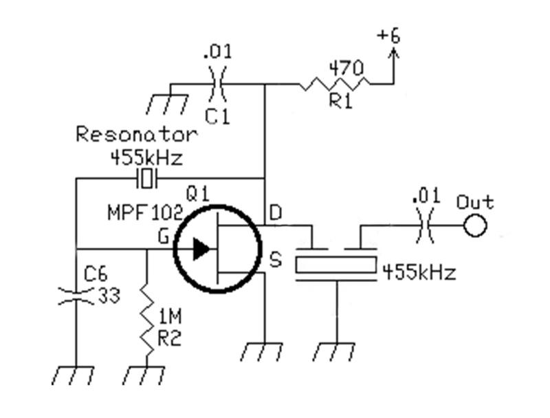
BFO Schematic?
Date: 01/30/18
I think the BFO circuit looks something like this (injection level pot on output not shown). I really don't remember exactly since I added it to the radio nearly 40 years ago!